The resulting optical signal is sampled by a photodetector, by splitting off a small percentage of the main optical signal output. The detected signal is filtered and amplified by a cascade of bandpass amplifiers centered on the BC control signal frequency. This detected bandpass filtered signal is then mixed with the original BC control signal to generate an error signal. The error signal is integrated and fed back to modulators phase bias electrode to drive the bias error to zero. With this scheme, I was able to control the bias point to within +/- 3o
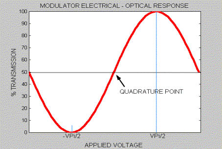
The purpose of an M-Z Bias Controller is to maintain an optical modulator's bias at the quadrature point. Along with amplitude control, bias control insures that the extinction ratio is maintained at its maximum level.
There are several different techniques, which can be applied to control the bias point of a modulator. Most use the non-linearity of the modulator to generate an error signal. This error signal is processed into a control signal and is fed back to the bias port of the modulator.
There are several different techniques, which can be applied to control the bias point of a modulator. Most use the non-linearity of the modulator to generate an error signal. This error signal is processed into a control signal and is fed back to the bias port of the modulator.
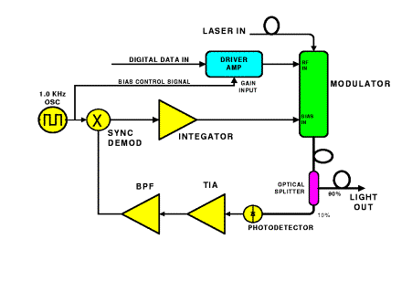
The controller consists of those items colored yellow.
The bias control scheme shown in the block diagram to the left, utilizes a null seeking control loop to keep the bias at the quadrature point. The bias controller outputs a small, low frequency AC signal that is connected to the driver amplifier gain control voltage pin. This signal amplitude modulates (AM) the digital data, which is then applied to the modulators RF input. The amplitude modulated data then amplitude modulates the optical carrier.
The bias control scheme shown in the block diagram to the left, utilizes a null seeking control loop to keep the bias at the quadrature point. The bias controller outputs a small, low frequency AC signal that is connected to the driver amplifier gain control voltage pin. This signal amplitude modulates (AM) the digital data, which is then applied to the modulators RF input. The amplitude modulated data then amplitude modulates the optical carrier.
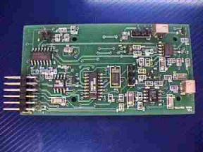
TYPICAL CONTROLLER
M-Z MODULATOR BIAS CONTROLLER
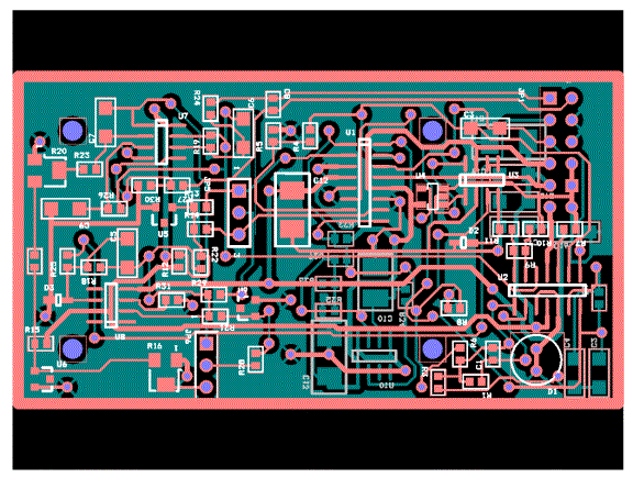
LAYOUT
An inexpensive two-layer board.
An inexpensive two-layer board.
THE BOARD